
An OPTICAL DELAY LINE is a critical element of any ultrafast pump-probe (or pump-gate) set-up. Even a small change in the beam pointing (laser beam drift, moved mirrors, etc.) can compromise the quality of your data. This is why it is recommended to check the delay line alignment at least once a day. Alignment of the delay line normally requires special technical training and can be time-consuming. Our patented Smart Delay Line™ system (USA Patent No.: 10,209,131 B2; USA Patent No.: 10,809,125 B2; USA Patent No.: 11,359,964 B2; China Patent No.: ZL201780003671.5; China Patent No.: ZL201680061777.6) fully restores the original alignment of your delay line in a few minutes. Very importantly, the original beam pointing after the delay line gets restored as well. This ensures that the optical setup “downstream” from the delay line will not require re-alignment. This significantly shortens the time needed to set up an experiment allowing for more up-time of the instrument. Additionally, this reduces the amount of technical training necessary for a user, thus making the spectrometer accessible to a larger group of researchers.
Time window
8 ns
Bi-directional repeatability
14 fs
Minimum step size
2.8 fs
Max. speed
>10 ns/s
Acceleration
260 ns/s2
Automated alignment time
3-5 min
Beam pointing drift at sample
<10 µm over 8 ns delay range
Max accepted beam diameter
27 mm (Ti:Sa) and 10 mm (Yb)
Correct alignment of an optical delay line is critical because the beam pointing after the delay line has to remain the same regardless of the position of the retroreflector. If the delay stage is not properly aligned, the beam pointing will change as the stage is translated. This will in turn affect the spatial overlap of the pump and probe beams in the sample and result in inaccurate data.
While there are commercially available solutions for active beam stabilization, they are not suitable for aligning an optical delay line in a pump-probe experiment. This is because the active stabilization method does not allow for pre-aligning an optical delay line. Instead, it actively compensates for any changes in the alignment in order to maintain the original beam pointing. In a pump-probe experiment, once the delay line scanning has started the incoming or outgoing beam trajectory should not be changed. Therefore an “on the fly” trajectory change will be unpredictably affected by how much the laser beam gets delayed by changing the position of the retroreflector. In other words, in a pump-probe experiment, the only optical element that can and should move is the optical delay line as the parameters of interest are measured as a function of the delay line position only. The only way to have a reliable correlation between the retroreflector position and the beam delay is to ensure that the delay line is aligned before the beginning of the scan.
Our patented Smart Delay Line™ feature (USA Patent No.: 10,209,131 B2; USA Patent No.: 10,809,125 B2; USA Patent No.: 11,359,964 B2; China Patent No.: ZL201780003671.5; China Patent No.: ZL201680061777.6) allows the user to automatically align the delay line before the experiment begins while maintaining the original beam pointing after the delay line. As a result, a user has a fully aligned delay line without the need to realign the rest of the setup. This saves a lot of time and drastically improves the user-friendliness of the spectrometer.
Features:
Fully automated and hands-off alignment of the delay line. Does not require any special training.
Automatically restores the original delay line alignment and the beam pointing after the delay line.
Typical alignment time is 3-5 min.
High level of precision, unattainable with manual methods. Beam pointing drift of <10 µm at sample position throughout an 8 ns delay range.
Most commercially-available delay lines use translation stages that are lead screw driven and therefore have rather limited translation speed and acceleration. As a result in a typical transient absorption or fluorescence upconversion experiment, a significant time is wasted on moving a retroreflector from one delay time point to another. This problem gets exacerbated when the time points are probed in random order. In this case, a typical experiment duration increases by a factor of 3 or more with most of the experiment time spent on moving the delay stage. This makes an otherwise very useful random delay-stepping approach impractical.
The Ultrafast Systems solution is to use a direct drive-based optical delay line that features a low-profile design with integrated, brushless linear motors. The direct-drive technology removes the need for a lead screw, eliminating backlash and internal flexible ducting ensures that cables cannot become trapped as the mechanism moves. Twin, precision-grooved linear bearings provide superior rigidity and linearity with excellent accuracy. This direct drive optical delay line covers an 8 ns time window. The delay line is compact enough to be located inside the main spectrometer housing. It is ideal for stepping delay time points in sequential or random order. Due to its large acceleration and high speed of translation, the overall experiment time remains essentially unchanged even when the time points are probed randomly.
In our optical delay line, the beam is sent through the delay line more than once. Multi-passing a delay line offers several advantages:
A shorter translation stage can be used. This makes the overall set-up more compact and allows for keeping the delay line closer to the sample and inside the spectrometer enclosure. This improves the beam pointing stability and data quality.
A shorter translation stage allows for faster travel between time points. This is very useful for random time stepping.
However, after multiple reflections off a protected metal retroreflector, a lot of the beam’s power gets lost and short fs pulses can get noticeably stretched. To overcome this problem, Ultrafast Systems’ delay lines utilize retroreflectors with chirp-corrected dielectric mirrors. This allows to preserve the laser pulse parameters as well as retain most of the power (~80%).
When a beam is routed through a delay line it is very important to avoid reflecting it off the seams in the retroreflector. When a laser beam hits a mirror seam in a corner of a retroreflector the reflected beam has a dark line appearing across the mode. Such a mode defect results in an unstable continuum which directly affects data quality. Even in a well-aligned delay line such a mode defect often results in a continuum flickering or disappearing with the translation of the delay track. The Ultrafast Systems proprietary delay line design ensures that a beam never hits a seam and the mode quality is always preserved.
The Ultrafast Systems optical delay line is compatible with the most commercially available femtosecond lasers. The two main types of femtosecond lasers used in pump-probe spectrometry are ~35 fs and ~100 fs. The figures below illustrate the time resolution that can be obtained with our delay line for each laser pulse duration. The traces in black represent a laser pulse, the red traces represent an IRF (Instrument Response Function) for an infinitely high-resolution optical delay line. The blue traces represent an IRF obtained with our delay line (14 fs resolution).
The first picture below illustrates a system resolution with a 100 fs laser pulse. Here the blue and the red traces are completely superimposed, indicating no difference between the shortest theoretical IRF and the IRF achievable with our delay line.
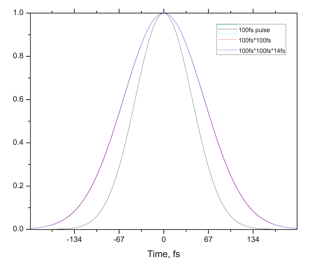
IRF simulation for 100 fs laser pulses
The picture below illustrates a system resolution with a 35 fs laser pulse. Here the blue and the red traces are very close together, corresponding to an increase of only ~2 fs from the shortest theoretically achievable IRF. Such an increase corresponds to only 4% of the shortest IRF of ~50 fs.

IRF simulation for 35 fs laser pulses
The resolution of an optical delay line indicates how accurately it can set a specific optical delay. This parameter should not be confused with the minimum step size. The resolution of a delay line is typically significantly larger than its minimum step size. Below are some brief explanations of what each parameter means.
Minimum step size:
This is the minimum possible incremental motion that a stage can make, otherwise known as a minimum step size. While this is an important parameter it should not be confused with the resolution of a translation stage. This is partly because a stage usually cannot arrive at an exact specified position due to backlash and other factors. Even when the encoder reading indicates the exact target position, the stage is still located within a certain distance from that position. This distance is determined by the repeatability of a stage.
Delay line resolution:
Resolution is what translation stage manufacturers refer to as “bi-directional repeatability”. Repeatability is a measure of the ability of the stage to return to an exact target position. The smaller the repeatability value, the closer the stage can get to a target. Bi-directional repeatability is an average of the repeatability when the target position is approached from both directions and is regarded as a more descriptive way of specifying repeatability. Ultrafast Systems uses translation stages based on direct-drive technology. Along with many other advantages (speed, acceleration), such stages do not have backlash and feature significantly better repeatability compared to lead screw-driven stages.
This site is protected by reCAPTCHA and the Google Privacy Policy and Terms of Service apply.
© 2002 – 2024 Ultrafast Systems, 8330 Consumer Ct, Sarasota, FL 34240, USA. All Rights Reserved.
An answer to your question might already be there.